Phase One Aerodynamic Research
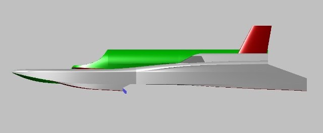
Following our initial research into what Reid Railton was proposing with his Crusader2 reverse 3 pointer design, our initial baseline design submitted for aerodynamic research was a 4 point hydroplane with a pair of closely coupled front sponsons and a pair of more widely spaced rear sponsons – which means the wake from the front causes minimum disruption to those at the rear. As with Railton’s reverse 3 pointer this also minimises front end lift. Our design starts as a displacement hull before rising onto sponsons. Finally, it “lifts off” clear of the water onto high speed hydrofoils. Initially we researched use of planing points attached to each of the sponsons but from our research and experience we know the amount of “nose up” before things become critical is very small and gets even smaller as speeds increase to Mach 0.6.
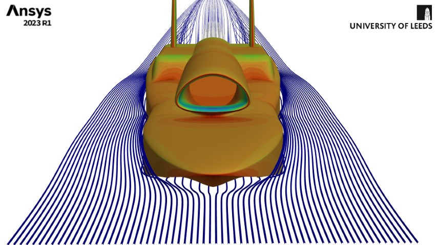
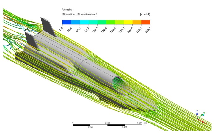
To help us research this, we are very fortunate to partner with the School of Mechanical Engineering at the University of Leeds and Imperial College London. Led by Dr Carl Gilkeson at Leeds, two teams of final year Aeronautical and Aerospace Engineering undergraduate students carried out a two year long program using ANSYS Fluent, a leading Computational Fluid Dynamics (CFD) software package. Running concurrently, Harrison Moss at Imperial College used another leading CFD package, StarCCM+, to do similar research, in parallel for some aspects, but also with more concentration on air intake design and the area between the water surface and the underbody. This provided a degree of correlation and cross checking between the two research programs. The results were interesting for a number of reasons but close enough in overall output to show that there was no major issue with either research program.
Aerodynamic Research Key Findings
The major points from the research are that the design has good directional stability and good roll stability right up to targets speeds. The less good news is that as suspected, at target speed we have a very small pitch angle window in which to operate before uncontrollable bow up pitch is encountered. This is crucial because we now have the numbers to show what we already believed. As the old phrase goes – without data you are just somebody else with an opinion. Now we have that data we can do something about it without having to guess and getting it badly wrong. What we do about it links directly to another key area of research – hydrodynamics, everything in the water rather than travelling over it.
Air Intake Design
The other area highlighted for more work was the air intake. This was initially designed using very basic parameters but knowing that it would need to be rechecked later using specialist expertise. There was some knowledge of airflow requirements of the Spey 205. We also knew a bit about it from using a pair for ThrustSSC. But even today, air intake design for fast jets is something of a black art allied to extensive research so we knew this would need more work.
The obvious question is why wouldn’t we use the air intake from an RAF Phantom since that’s where the engine came from? The answer is that the Phantom intake uses ramps and fences to vary and control airflow up to high supersonic speeds. Removing those to suit our Mach 0.6 target speed ruins the integrity of the intake design. So why not use an intake from a subsonic design such as the Buccaneer since that also uses a Spey? That’s because Buccaneers and other subsonic designs use a Spey without reheat, the air intakes of which will not provide the airflow for a Spey on full reheat.
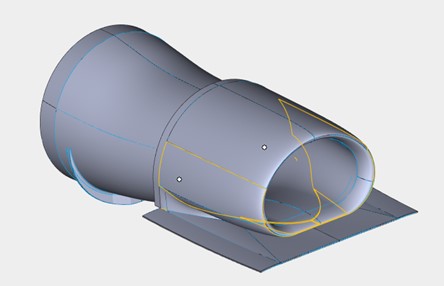
The aerodynamic results showed air spilling out of the top section of the intake which in turn upset the overall air flow around the top of the craft. With the intake design affecting not only the air flow to the engine but also around the outside of the craft – to a greater degree than originally anticipated – the air intake design took on a higher priority. Again, now we know what the numbers are we have revised the design which is much smaller, flatter on top and extended forward slightly. It is very similar to the intake used on an F-16 and has been CFD tested from the area immediately ahead of the intake right through to the compressor face. Finally, we reran the overall shape aero CFD research with the revised intake to confirm the finalised shape.